COMMERCIAL BOARDWALK / FIELD RESOURCE
Fastening for a maintainable public surface
Compare exact systems by profile fit, exposure evidence and access for future work.
Updated
Build a project planning summary ↗
04 / DESIGN FOR THE NEXT INTERVENTION
One board.
A whole access decision.
Move one board through the repair story. The camera and surrounding promenade stay fixed. Each step brings a different decision and record.
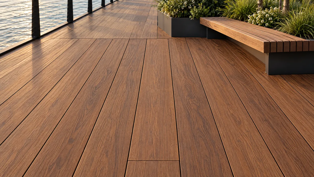
Surface movement is explanatory. It does not prescribe a lifting method, construction sequence, board size or connection.
STEP 1 / 6 · In service
Locate the work
Start with a location, not a loose replacement board. Identify the route segment, board and surrounding furniture in the installed-system record.
- Coordinate with
- Owner / operator
- Keep the record
- Location reference + original installation record
Can the same board be found again without relying on this image?
What must be resolved below the surface?
Identify the installed attachment before selecting a removal method. The image intentionally leaves clips, screw paths and support design unresolved.
Review the field-board interface ↗Specify a complete connection
A commercial fastening review starts with the board and the support it joins. Record the actual profile, supplied material condition, selected accessory, screw configuration and substrate. Then add the exposure and board role. Field boards, perimeter pieces and removable panels may present different questions within the same surface.
The Forest Products Laboratory’s fastening chapter explains why connections must account for wood properties along and across the grain and for dimensional changes associated with moisture. That principle supports a complete-system review. It does not supply a universal boardwalk screw, clip or fastening schedule.
Compare visible and hidden attachment through access
A hidden-fastener surface conceals some of the connection in or below the board interface. A face-fastened surface presents a different access condition. Compare the actual selected systems, including how work is performed at an edge and how a field board is replaced. Do not treat either appearance as an automatic maintenance advantage.
Ask the system provider to identify the applicable instructions for the exact board and substrate. For a grooved board, compare the documented groove geometry with the accessory requirement; nominal board size does not establish fit. For through-board fastening, obtain the system-specific preparation and screw information instead of borrowing the hidden-system detail.
Keep metals and exposure evidence attached to the SKU
Record product identifiers for screws, clips and other accessories separately. Verify their material and exposure documentation against the proposed environment and support, including treatment information where relevant. A stainless-steel description without the required product detail can leave a review unfinished.
Include adjacent metal interfaces in the project coordination. Furniture and guard attachments may occupy the same area as decking accessories while belonging to a different assembly. Keep those responsibilities distinct and request the documentation needed for each interaction. This page does not choose an alloy or approve preservative compatibility.
Make the mockup answer a replacement question
Use a representative field condition and at least one relevant edge or interruption. Record the board, profile, fastener system, substrate and document revisions. Ask the installer to demonstrate the proposed system-specific access sequence under the approved mockup scope.
Record what must be reached, which adjacent parts are involved and whether removal changes any consumable or replaceable accessory. Include the tools and access assumed by the procedure. The owner needs to understand the work footprint and operating implications, not merely see that a clip disappears beneath the boards.
Fictional example: a neat field connection becomes hard to reach when a fixed bench is added. The mockup should carry that interface into the review before installation. It is easier to resolve the detail then than to discover the access dependency during an occupied-site repair.
Keep takeoff and fastening design separate
Once the accepted connection layout is available, use it to develop the accessory quantity. Field intersections are only one part of the order; starts, ends, board joints, borders, transitions, stairs, spares and package rounding may need separate treatment. Keep their basis visible.
A geometric intersection count does not establish where fasteners are structurally required. Do not multiply a generic clip rate by the entire surface area and call it an approved schedule. Keep the reviewed design, manufacturer instructions and quantity calculation linked so a later profile or layout change triggers the relevant review.
Use Fastener Compatibility for exact-system evidence and unresolved mechanical questions. Use the commercial planner for the surface scope and operating record. Carry the accepted connection references into closeout so future repairs begin with an identifiable system.